HH pulse quit last week. Made a lot of noise then went silent. I opened it up and there is a yellow wire coming from the coil connector that is hanging loose. I looked for places that might look like it was connected and I am not seeing things that looked soldered that not longer are. Any help is much appreciated. I am cross posting this in the both the beach and technology forums. If I get an answer in one, no need to post in the other. Thanks!

Find's Treasure Forums
Welcome to Find's Treasure Forums, Guests!
You are viewing this forums as a guest which limits you to read only status.
Only registered members may post stories, questions, classifieds, reply to other posts, contact other members using built in messaging and use many other features found on these forums.
Why not register and join us today? It's free! (We don't share your email addresses with anyone.) We keep email addresses of our users to protect them and others from bad people posting things they shouldn't.
Click here to register!
Need Support Help?
Cannot log in?, click here to have new password emailed to you

You are using an out of date browser. It may not display this or other websites correctly.
You should upgrade or use an alternative browser.
You should upgrade or use an alternative browser.
HH Pulse wire came loose. Where does it go?
- Thread starter tvr
- Start date
River Raider
Well-known member
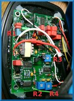
Had circuit board pictures at one point. PM me or post a large picture of the top of the circuit board. I may then remember where it goes.
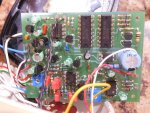
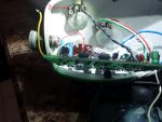
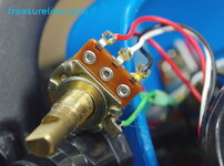
The red and white wires (partly hidden by the capacitor) go into feed thru holes marked "coil". The red, white and yellow wires come from the coil connector. I don't see another place on the board that looks like a place that was soldered that is missing something. All the thru holes have something soldered in except the one marked test point (TP 0).
Attachments
OldBeechnut
Well-known member
River Raider
Well-known member
There's 3 wires coming off a mono coil.
Start of the coil wire, end of coil wire and shield wire.
Guessing from what I see, if you have a multi meter, see if you have continuity between the red and yellow wire and red and white wire. The ones that do will be the start and end wire.
The last wire is the shield wire which goes to ground. So the yellow wire probably goes to ground. Look for another solder pad under the circuit board near the white wire that connects to the white solder pad.
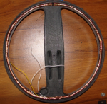
When I build my coil, see picture. White wire is the coil bundle wires start and end, Yellow wire is attached to the shield-copper tape. One white coil wire is connected with the shield yellow wire, which can be done at the circuit board or within the coil
Start of the coil wire, end of coil wire and shield wire.
Guessing from what I see, if you have a multi meter, see if you have continuity between the red and yellow wire and red and white wire. The ones that do will be the start and end wire.
The last wire is the shield wire which goes to ground. So the yellow wire probably goes to ground. Look for another solder pad under the circuit board near the white wire that connects to the white solder pad.
When I build my coil, see picture. White wire is the coil bundle wires start and end, Yellow wire is attached to the shield-copper tape. One white coil wire is connected with the shield yellow wire, which can be done at the circuit board or within the coil
Attachments
"There's 3 wires coming off a mono coil. Start of the coil wire, end of coil wire and shield wire." ... " shield wire which goes to ground"
That is what I was thinking. The battery wires (from the other side of the headphones) come into one of the pots then to the + - on the circuit board. I'll tack the yellow to the negative at the pot and see what happens.
Thanks! I needed the verification that the third wire was a shield and not some center tap that I saw nowhere to put.
Frustration! Ohmed it out through the battery terminal to the pot with the on/off switch, ready to connect it and ... I can find my soldering gun, but not either my 15 watt iron (the perfect tool for this) or my 25 watt iron. I'm not going in there with the gun as I'm very likely to melt about 4 wires and who knows what other damage the massive heat of the gun may do. Going to walk away for now and on the next trip to run errands will pick up a cheap iron.
Wire connected to point that ohms out as ground for the circuit card and negative on one of the two 9V battery terminals (they are wired in series, so circuit must run on around 18 volts. Put batteries in and turn it on ... nothing; then notice batteries are getting hot, fast. This detector may have seen it's last use.
Thanks for the help Sven and OBN; at least we tried.
Thanks for the help Sven and OBN; at least we tried.
Sven,There's 3 wires coming off a mono coil.
Start of the coil wire, end of coil wire and shield wire.
Guessing from what I see, if you have a multi meter, see if you have continuity between the red and yellow wire and red and white wire. The ones that do will be the start and end wire.
The last wire is the shield wire which goes to ground. So the yellow wire probably goes to ground. Look for another solder pad under the circuit board near the white wire that connects to the white solder pad.
When I build my coil, see picture. White wire is the coil bundle wires start and end, Yellow wire is attached to the shield-copper tape. One white coil wire is connected with the shield yellow wire, which can be done at the circuit board or within the coil
When I pulled the connector apart that goes into the headset, I saw that the cable coil is a coax/ Both the yellow and the white wire was soldered to the shield. The red wire as well as the white wire (center conductor and shield) went to the circuit board where the board has two contact pads labeled coil.
What I don't know yet is if the other wire (yellow) is supposed to go to ground (battery negative) or somewhere else.
That would be much appreciated. Am particularly interested in where the third wire from the coil wire goes. Two go to the circuit card where the card says coil; but the third wire is the one I'm not sure about.TVR :
Did you ever figure out where the wire went. I have two HH Pulse machines. I can open them up and send you a picture of where the wires go .
Jeff
OkinawaHunter
Member
I have a Headhunter Diver (Yellow model) and one of the 2 green wires came loose in mine and I soldered it on to other green wire on the sensitivity pot and now I get no signal at all.
Does anyone have a picture or diagram where this wire might go?
Does anyone have a picture or diagram where this wire might go?
Right now it is still dead. I've got a replacement mosfet, but have not done the swap out.If this yellow wire were the shield the detector would still work with it disconnected. Does it?
River Raider
Well-known member
I have a Headhunter Diver (Yellow model) and one of the 2 green wires came loose in mine and I soldered it on to other green wire on the sensitivity pot and now I get no signal at all.
Does anyone have a picture or diagram where this wire might go?
Attachments
If you by chance in Orange County, CA I could look at it for you.Right now it is still dead. I've got a replacement mosfet, but have not done the swap out.
Thanks for the offer. I'm one the other coast. I'm working on learning the Impulse AQ and have put the HHPulse on the back burner for now.If you by chance in Orange County, CA I could look at it for you.